Hole basis and shaft basis system pdf
The fundamental IT deviation for hole basis is designated by “H”, the shaft designated by “h”. Tolerance Symboles: The tolerance symbol is established by combining the IT grade number and position letter for tolerance.
Hole basis limits and fits with Shaft basis limits and fits have been given as an example in the chart below. The definitions for descriptions given in the chart …
Hole Basis system b. Shaft Basis system Clearance fit Transition fit Interference fit Transition fit Interference fit Clearance fit Fig. 7 [a-b] Systems of Fit. Schematic for grades in Indian Stds. 11 Disposition of all the shafts and holes with reference to the zero line. Limits and Fits – Definitions Holes A D H P V Z Zc FD Zero line 12 Shafts a d h p v z zc FD Zero line Schematic of
1.2 Interrelation among Tolerance Ranges for Generally Used Hole-basis System of Fits 2.2 Interrelation among Tolerance Ranges for Generally Used Shaft-basis System of Fits * Values in cases where the measurement exceeds the reference dimension 18 mm, but does not exceed 30 mm. * Values in cases where the measurement exceeds the reference dimension 18 mm, but does not exceed 30 mm. (μm
In this shaft basis system the size of the hole is obtained by adding the allowances to the basic size of the shaft. The system gives design of the hole. Then tolerance are applied to the each part separately. The shaft basis system the upper deviation of the shaft is zero and these system …
Example 3 • determine the shaft and hole limits for: – – – – hole-basis system a medium drive fit a basic diameter of 96 mm use a preferred size EML 2023 Computer Aided Design 32 . 33 . Example 3 • use a preferred basic diameter of 100 mm • use a fit of H7/s6 EML 2023 Computer Aided Design 34 .
—200 * This table shovs the case when basic size is over 18mm to 30mm. —50 * This table shows the case when basic size is over 18mm to 30mm. SYSTEM OF LIMITS AND FITS
In the hole basis system, the size of the hole is kept constant and shaft sizes are varied to obtain various types of fits. In this system, lower deviation of hole is zero, i.e. the low limit of hole is same as
shaft chosen as a basis for a shaft-basis fit system SEE: 3.4.1.2 Note 1 to entry: For the purposes of the ISO code system, a basic shaft is a shaft for which the upper limit deviation is zero.
Fits and Tolerances KSU Faculty

[Technical Data] Basis of Fitting Selection / Dimensional
1.2 Mutual relationship between tolerance range and hole base fitting which are in constant use. [Note]* Fits will make an exception according to the classification of dimensions. 2.2 Mutual relationship between tolerance range and shaft base fittings which are in constant use.
Hole basis system: The size of the shaft is obtained by subtracting the allowance from the basic size of the hole. Tolerances are then applied to each part separately. In this system, the lower deviation of the hole is zero. The letter symbol indication for this is ‘H’.
https://www.nbk1560.com https://www.nbk1560.com Datum hole Tolerance zone class for shaft Clearance fi t Transition fi t Stationary fi t H6 g5 h5 js5 k5 m5
HOLE BASIS SYSTEM: In this system, the hole is kept as a constant member and different fits are obtained by varying the shaft size. BASIS OF LIMIT SYSTEM SHAFT BASIS SYSTEM: In this system, the shaft is kept as constant member and different fits are obtained by varying the hole size.
shaft tolerance classes used on a regular basis in the world. Considering each requires Considering each requires one class of hub to achieve an interference fit and another to achieve a clearance fit, it
The hole-basis system of fits is more economical than the shaft-basis system as only one size of drill is used to produce differ ent fits, the shafts being turned and ground to the required sizes, thus making manufacture and measurement much easier.
The pin is 10mm in diameter. The pin is nominated so use the shaft basis system. The rod has a nominal width of 20mm. Once again the rod is nominated so use the shaft basis system.
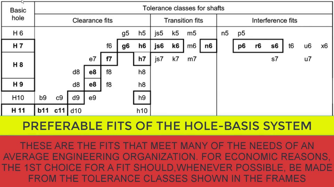
The following tables report the preferred metric fits and tolerances for hole and shaft basis systems given by the ISO 286-1 (2010) and ANSI B4.2-1978 standards. The use of these tolerances is advised for economic reasons.
As a mechanical design engineer you may have to design a shaft or mating hole component or both. For such design assignments, you have to decide the GD&T limits and fits, and for deciding the limits and fits, you have to decide whether you want to go with the hole basis system or the shaft basis system.
Hole Basis: In the hole basis system the hole is produced to a fixed size. Then the Then the shaft is made to whatever size is necessary to produce the type of fit required.
Hole Basis Fit System: A fit system in which hole lower deviation is zero. In other words the lower limit of size of hole is equal to nominal size. The required fit (clearance, interference etc.) is obtained by keeping hole as defined and applying various tolerance classes to shaft.
Hole basis is the system of fits where the minimum hole size is the basic size. The fundamental deviation for a hole basis system is indicated by the uppercase letter “H”. Shaft basis is the system of fits where the maximum shaft size is the basic size. The fundamental deviation for a shaft basis system is indicated by the lowercase letter “f”. 23. Metric Tolerance Symbols Combining
understanding of Hole Basis Limits and Shaft Basis Limits. Some of the application and some of the Some of the application and some of the selected Preferred Fits for Hole and Shaft Basis system have been given followed by Fits explanations.
thehole-basisseries,toholetolerancesof1,lj^,3,and10fitunits and in the shaft-basisseriestoshaft tolerances of 1,1, 3, and 10 fit units,respectively; one fit unit (Passeinheit) beingequal to 0.005^5
hole basis, shaft basis and keyway tolerances and fits dimensioning conventions representing aeronautical components and systems using sketching and computer graphics
hole and shaft tolerance chart download limits fits tolerances calculator system basis,shaft and hole tolerance chart inches pdf chapter 7 tolerances,hole shaft tolerance chart pdf and download inches what is the fit are different types of fits,hole basis and shaft tolerance chart download basics of interchangeability pdf,shaft and hole tolerance chart inches standard limits fits tutorial
The following defines the preferred tolerance basis for hole and shaft per. ISO 286. Open ISO 286 Table of Hole & Bore Tolerances Calculator Open ISO 286 Table of Shaft Tolarences Calculator General ISO Geometrical Tolerances Per. ISO 2768
The figure (a) shows the hole-basis system of preferred fits and the figure (b) shows the shaft-basis system of preferred fits (b). MEE270, KIM, NIU 26. The preferred basic size for computing tolerances are given in Table 11.2 (p.371). Basic diameters should be selected from the first-choice column since these are readily available stock size for round, square, and hexagonal products. 11-11
ALLOWANCES AND TOLERANCES 646 is given in Table 11 . Normally, the hole basis system is preferred; however, when a com-mon shaft mates with several holes, the shaft basis system …
What is The System of Fits and Basis System mechcadcam.com
It is better to select hole basis fit. Because it is better as the production of shafts to the required size is easier. But, the shaft basis system is very good for manufacturing bright drawn bars. Because it is better as the production of shafts to the required size is easier.
Hole:-Refers to diameter of a circular hole as well as to any internal dimension of component .it is referred as “female” Basic Hole size Shaft Shaft:-Limits and fits, all external features of a component including those which are not cylindrical are designated as ‘Shaft. It is referred as “male”
H6 tolerance chart, Iso tolerance chart pdf, H6 shank tolerance chart, Iso hole tolerance chart, Metric h6 tolerance, What is h7 tolerance, Iso tolerances for holes, Bearing tolerances shaft and housing, Sra reading level chart, Sra corrective reading series, Sra decoding and comprehension, Sra corrective reading ordering, Corrective reading placement test, Sra reading mastery placement tests – wine folly wine and cheese pdf The designation means that the nominal size of the hole and the shaft is 50 mm. H is the nature of fit for the hole basis system and its fundamental deviation is zero.
Section 1, Conditions: Determine the fit type for the Hole-basis system or the Shaft-basis system of fits. A similar fit is calculated automatically if the option is checked in the More Options area when the fit
Ahmed Kovacevic, City University London Design web 7 Shaft design Free body diagram Free body diagram is calculated such that the system of interest is separated from the
• Hole Basis/ Shaft Basis system . Types of Fits . Clearance Fit – Hole Basis . Transition Fit –Hole Basis . Interference Fit – Hole Basis . Typical Recommended Fits Clearance Fits H7/h6 : Sealing rings, bearing covers H7/g6 : Sleeve shafts, clutches H7/f7 : High speed bearings, machine tool spindles Transition Fits H7/n6 : Gears and bearing bushes, shaft and wheel H7/m6 : Gears belt
Shaft Basis system: If the system of assembly of shaft and hole consisting of basic shaft, then that type of system is known as Shaft Basis System. It means for the assembly of shaft and hole, the zero line will be lying on the maximum size of the shaft as shown. For this system the Upper Limit Size of shaft is equal to the Basic Size.
other is the shaft basis. In the hole basis system the dimension of the hole is considered to be the datum, whereas, in the shaft basis system dimension of the shaft is considered to be the datum. The holes are normally made by drilling, followed by reaming. Therefore, the dimension of a hole is fixed due to the nature of the tool used. On the contrary, the dimension of a shaft is easily
hole basis and shaft tolerance chart. hole shaft tolerance chart pdf module 1 measurements limit fit skill 4 sure basis and,shaft and hole tolerance chart inches basis system engineering download,shaft and hole tolerance chart inches module 1 measurements limit fit skill 4 sure download,hole and shaft tolerance chart download inches basis true
But in a shaft based system measuring a hole requires many standard dimension gauges which increases the cost which could be of rework or scrapping and it is also time consuming. Hence having a standard hole based system is more efficient than shaft based system.
systems have been in use for several years. These reflect preferred sizes for components such as threaded fasteners, steel plates, sheets, and bars used through-out the world. The accompanying table, Selecting a Preferred Size shows how the general system works. For example, if a designer was choosing a hydraulic cylinder, bolt, or plate thickness, the sizes in the First-choice column would be
PREFERRED FITS ANSI B4.2 specifies the ten hole and shaft basis fits as shown in Table 6-1 and as illustrated in Fig. 6-4. Each of the ten hole basis fits corresponds to a shaft basis fit with equal clearances for the same nominal size.
20. Basic shaft (the shaft chosen as a basis for the shaft basis system of fit) 21. Basic hole (the hole chosen as a basis for the hole basis system of fit)
T o determine the system tolerances for the shaft and the hole, add the piece tolerances of .003” and .003” to get .006” The parts are dimensioned on the drawing. The upper limit of the hole is determined by adding the tolerance of the part to .500”.
Basic shaft system Drafting Reference Training Manuals
Assertion (A): Hole basis system is generallypreferred to shaft basis system in tolerance designfor getting the required fits.Reason (R): Hole has to be given a larger toleranceband than themating shaft.(a) Both A and R are individually true and R is thecorrect explanation of A(b) Both A and R are individually true but R is not thecorrect
Shaft basis system keyword after analyzing the system lists the list of keywords related and the list of websites with related content, in addition you can see which keywords most interested customers on …
Find equivalent fit when changing between Hole-basis and Shaft-basis. When you select a shaft fit symbol In the Tolerance Zones area (fit symbols are in a graphic form), the Hole-basis fit system and ‘H’ fit symbol is set automatically.
—The basic shaft system. In the illustration, the maximum shaft size is the basic size. To obtain the minimum hole diameter, assume an allowance of .003 inch and add that to the basic shaft size.
For example, if a shaft with a nominal diameter of 10 mm is to have a sliding fit within a hole, the shaft might be specified with a tolerance range from 9.964 to 10 mm (i.e., a zero fundamental deviation, but a lower deviation of 0.036 mm) and the hole might be specified with a tolerance range from 10.04 mm to 10.076 mm (0.04 mm fundamental deviation and 0.076 mm upper deviation).
Hole Basis and shaft basis system: In identifying limit dimensions for the three classes of fit, two systems are in use: Hole basis system : The size of the shaft is obtained by subtracting the allowance from the basic size of the hole.
ANSI Limits and Fits Calculator amesweb.info

Module Mechanical Engineering
The standardized nomenclature of the shaft/hole fittings differentiates between hole basis and shaft basis fits. The fits are two digit letter/number designations where the hole basis fits are noted with a capital letter (H7) while the shaft basis fits are noted with a lower case letter (h7). This is the most important concept to remember when sorting through the shaft/hole fit specifications
Hole basis limits and fits with Shaft basis limits and fits have been given as an example in the chart below. The definitions for descriptions given in the chart explained as follows. The chart below gives simple understanding of Hole Basis Limits and Shaft Basis Limits. Some of the application and some of the selected Preferred Fits for Hole and Shaft Basis system have been given followed by
The chart below gives simple understanding of Hole Basis Limits and Shaft Basis Limits. Some of Some of the application and some of the selected Preferred Fits for Hole and Shaft Basis system have been given followed by Fits explanations.
4.1 Hole basis fit system is used in mechanical engineering, machine tools and cars because it is easier to produce different exact shaft diameters than to produce different exact hole diameters.
Shaft basis system: In this system, the different clearances and interferences are obtained in associating various holes with a single shaft, whose upper deviation is zero. 1.6 Selection of Fits Hole basis system is the most commonly used system because due to the fixed character of hole production tools, it is difficult to produce holes with odd sizes.
• Hole Basis fit: the basic size is on this • Shaft Basis fit: the basic size is the maximum dia of the shaft and the fit is calculated base on this Basic hole and shaft system-Imperial size Hole Basis Fit Interference fit Clearance fit Shaft Basis Fit Interference fit Clearance fit Basic Size .500 Largest shaft .500 Smallest hole .500 . 0.500 is the lower limit hole 0.496 is the upper
In hole basis system, the size of the hole is constant and different fits are obtained by varying the size of shaft as shown in Fig. 1.57 (a). It may be noted that, from manufacturing point of view, a hole basis system is always preferred.
The shaft will have the least possible amount of metal at a lower limit of 39.95 mm, and this limit of the shaft is known as minimum or least metal limit (LML). Similarly, consider a hole having a …
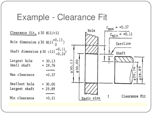
—The basic hole system. In the illustration, the minimum hole size is the basic size. To calculate the maximum diameter of the shaft, assume an allowance of .003 inch and subtract that from the basic hole …
I SELECTING A PREFERRED SIZE Timing Belts and Pulleys

Limitstolarence and fits SlideShare
Fits and Tolerances PowerPoint Presentation SlideServe


Design web ME 1110 – Engineering Practice 1 Introduction
Assertion (A) Hole basis system is generallypreferred to
wine grape varieties in california pdf – AUTODESK AUTOCAD INVENTOR 2012 DESIGN ACCELERATOR
Hole Basis system and Shaft Basis System Engineering


On Hole And Shaft We Will Need A Thick Volume Book But
H6 Tolerance for Shaft PDF documents – Docucu-Archive.com
Hole Basis Limits and Fits With Shaft Basis Limits and
Comparison of American British and German standards for
Hole Basis and shaft basis system: In identifying limit dimensions for the three classes of fit, two systems are in use: Hole basis system : The size of the shaft is obtained by subtracting the allowance from the basic size of the hole.
1.2 Mutual relationship between tolerance range and hole base fitting which are in constant use. [Note]* Fits will make an exception according to the classification of dimensions. 2.2 Mutual relationship between tolerance range and shaft base fittings which are in constant use.
Section 1, Conditions: Determine the fit type for the Hole-basis system or the Shaft-basis system of fits. A similar fit is calculated automatically if the option is checked in the More Options area when the fit
Find equivalent fit when changing between Hole-basis and Shaft-basis. When you select a shaft fit symbol In the Tolerance Zones area (fit symbols are in a graphic form), the Hole-basis fit system and ‘H’ fit symbol is set automatically.
• Hole Basis/ Shaft Basis system . Types of Fits . Clearance Fit – Hole Basis . Transition Fit –Hole Basis . Interference Fit – Hole Basis . Typical Recommended Fits Clearance Fits H7/h6 : Sealing rings, bearing covers H7/g6 : Sleeve shafts, clutches H7/f7 : High speed bearings, machine tool spindles Transition Fits H7/n6 : Gears and bearing bushes, shaft and wheel H7/m6 : Gears belt
The standardized nomenclature of the shaft/hole fittings differentiates between hole basis and shaft basis fits. The fits are two digit letter/number designations where the hole basis fits are noted with a capital letter (H7) while the shaft basis fits are noted with a lower case letter (h7). This is the most important concept to remember when sorting through the shaft/hole fit specifications
Shaft basis system keyword after analyzing the system lists the list of keywords related and the list of websites with related content, in addition you can see which keywords most interested customers on …
The hole-basis system of fits is more economical than the shaft-basis system as only one size of drill is used to produce differ ent fits, the shafts being turned and ground to the required sizes, thus making manufacture and measurement much easier.
shaft chosen as a basis for a shaft-basis fit system SEE: 3.4.1.2 Note 1 to entry: For the purposes of the ISO code system, a basic shaft is a shaft for which the upper limit deviation is zero.
Hole:-Refers to diameter of a circular hole as well as to any internal dimension of component .it is referred as “female” Basic Hole size Shaft Shaft:-Limits and fits, all external features of a component including those which are not cylindrical are designated as ‘Shaft. It is referred as “male”
T o determine the system tolerances for the shaft and the hole, add the piece tolerances of .003” and .003” to get .006” The parts are dimensioned on the drawing. The upper limit of the hole is determined by adding the tolerance of the part to .500”.