
network cable code color pdf
Network cable color coding provides a consistent method for wiring Ethernet cables, ensuring reliable connections and simplifying installations. This system assigns specific colors to wires within cables, helping technicians avoid errors and maintain organization. The T568A and T568B standards are widely used, differing primarily in the arrangement of green and orange wire pairs. Proper color coding is essential for ensuring optimal performance in network setups, from home offices to large data centers.
Overview of Ethernet Cable Color Codes
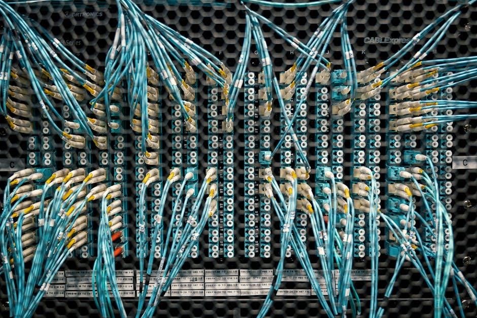
Ethernet cable color codes are standardized to simplify wiring and ensure consistency in network installations. Each cable contains eight colored wires, arranged in four pairs, with specific colors assigned to each wire. The T568A and T568B wiring standards dictate the order of these colors, differing mainly in the placement of green and orange pairs. For example, T568A assigns green to pins 1 and 2, while T568B swaps green with orange. This standardized approach reduces errors and ensures reliable data transmission. Color coding also aids in identifying cable types, such as Cat5, Cat6, and Cat7, which vary in data transfer capabilities. Proper adherence to these codes is essential for maintaining network performance and scalability.
Importance of Color Coding in Network Cables
Importance of Color Coding in Network Cables
Color coding in network cables is essential for ensuring consistency, reducing errors, and simplifying installations. By standardizing wire colors, technicians can quickly identify pairs and connections, minimizing the risk of miswiring. This consistency is critical for maintaining network performance and reliability. Proper color coding also aids in troubleshooting, as it allows for easy verification of wire connections. Additionally, it helps in organizing cables, making it easier to identify specific cables in complex setups. Without color coding, network installations would be prone to errors, leading to connectivity issues and reduced efficiency. Thus, color coding plays a vital role in ensuring seamless communication and optimal functionality in Ethernet networks.

T568A and T568B Wiring Standards
T568A and T568B are common wiring standards for Ethernet cables, differing in the arrangement of green and orange wire pairs. They ensure reliable network connections.
Differences Between T568A and T568B
The primary difference between T568A and T568B wiring standards lies in the arrangement of the green and orange wire pairs. In T568A, the green wire is paired as the second pair, while the orange wire is the third pair. Conversely, in T568B, the orange wire is the second pair, and the green wire is the third pair; Both standards are part of the EIA/TIA 568 specification and are compatible with Category 5, 6, and 7 cables. The choice between T568A and T568B depends on specific networking requirements or organizational preferences, as both configurations support the same data transmission capabilities. Consistency in using one standard throughout a network is crucial to avoid connectivity issues.
Pin-Out Layout for Straight-Through Cables
Straight-through cables use the same wiring configuration on both ends, following either the T568A or T568B standard. For T568A, the pin-out layout is: blue, blue-white, green, green-white, orange, orange-white, brown, and brown-white. In T568B, the layout is: orange, orange-white, green, green-white, blue, blue-white, brown, and brown-white. Both configurations are compatible with Category 5, 6, and 7 cables. The key difference lies in the second and third pairs, where T568A uses green and T568B uses orange. Properly following these layouts ensures reliable data transmission and minimizes interference. Consistency in using one standard across a network is essential to avoid connectivity issues.
Creating Ethernet Cables
Creating Ethernet cables involves stripping, arranging wires, and crimping connectors. Follow T568A or T568B standards for proper wire arrangement to ensure reliable network connections and performance.
Step-by-Step Guide to Making Straight-Through Cables
To create a straight-through Ethernet cable, start by cutting the required length of Cat5, Cat6, or Cat7 cable. Strip the outer jacket using a cable stripper, exposing about 1-2 inches of the inner wires. Carefully arrange the wires according to the T568A or T568B standard, ensuring the color sequence is consistent at both ends. Insert the wires into an RJ45 connector, making sure each wire is seated properly. Use a crimping tool to secure the connector in place. Finally, test the cable using a cable tester to verify all pins are correctly connected and functioning. This ensures a reliable and high-performance network connection.
How to Make Crossover Cables
Crossover cables are used to connect similar devices, such as computer-to-computer or hub-to-hub. To make one, cut the cable to the desired length and strip the outer jacket. Arrange one end according to the T568A standard and the other end using the T568B standard. This means swapping the green and orange wire pairs between the two connectors. Insert each end into an RJ45 connector, ensuring the wires align correctly. Crimp the connectors firmly using a crimping tool. Test the cable with a network cable tester to confirm proper connectivity. This ensures the cable can handle data transmission between similar devices without the need for a crossover switch, providing a reliable direct connection.

Applications of Network Cable Color Codes
Network cable color codes are essential for Power over Ethernet (PoE), enabling power and data transmission. They also play a key role in Cat5, Cat6, and Cat7 cables, ensuring reliable connections and high-speed data transfers across networks.

Use in PoE (Power over Ethernet) Cables
Power over Ethernet (PoE) cables rely on network cable color coding to deliver both power and data through a single Ethernet cable. The T568A and T568B standards define specific color assignments for wire pairs, ensuring compatibility with PoE devices. In PoE systems, the spare pairs (typically blue and brown) are used to carry power, while the green and orange pairs handle data transmission. This separation prevents interference and ensures efficient power delivery. Color coding simplifies the installation and troubleshooting of PoE-enabled devices, such as IP cameras and wireless access points. By adhering to these standards, technicians can maintain reliable connections and optimize network performance.
Role in Cat5, Cat6, and Cat7 Cables
Network cable color coding plays a crucial role in Cat5, Cat6, and Cat7 cables by ensuring proper wire pair identification and maintaining performance standards. These cable categories support higher data rates and frequencies, requiring precise wiring to minimize interference. The T568A and T568B standards provide color-coded guidelines for wiring, ensuring consistent connections across all cable types. In Cat5, for example, the color scheme helps distinguish between data and unused pairs, while in Cat6 and Cat7, the coding ensures tighter twist rates and better shielding for reduced crosstalk. This standardized approach guarantees reliable data transmission and maintains the integrity of high-speed networks, making color coding indispensable for modern Ethernet installations.
Best Practices for Network Cabling
Adhere to T568A/B standards, ensure proper cable management, and label connections clearly. Regularly test cables and maintain organization to prevent signal loss and ensure optimal performance.
Common Mistakes to Avoid
One of the most frequent errors in network cabling is incorrect wire arrangement according to T568A/B standards, leading to connectivity issues. Mixing up green and orange pairs is particularly common. Improper stripping of cable jackets can expose or damage wires, causing signal loss. Forgetting to test cables after installation is another oversight, which can result in hidden faults. Additionally, neglecting to label cables and ports can lead to confusion and misconnections down the line. Using cables of insufficient quality or incorrect category (e.g., Cat5 instead of Cat6) can also hinder performance. Ensuring precise wiring and thorough testing helps minimize these pitfalls.
Testing and Validation of Ethernet Cables
Testing and validation are crucial steps to ensure Ethernet cables function correctly. Use a cable tester to verify continuity, check for opens, shorts, or wiring errors, and confirm proper pin-to-pin connections. Wiremap testers can identify miswired or damaged pairs, while network diagnostic tools can test signal strength and data transmission. Always test cables before installation to avoid costly rework. For Power over Ethernet (PoE) cables, ensure proper power delivery and data transmission. Regular testing helps maintain network performance, identify potential faults, and prevent downtime. Following best practices ensures reliable connections and optimal network functionality.

Resources and Downloads
Download free PDF guides for network cable color codes, including diagrams and wiring standards. Access online tools for creating custom cable wiring diagrams and testing checklists.
Free PDF Guides for Network Cable Color Codes
Download comprehensive PDF guides detailing network cable color codes, including T568A and T568B wiring standards. These resources provide clear diagrams, pin-out layouts, and step-by-step instructions for creating Ethernet cables. Ideal for professionals and DIY enthusiasts, they cover topics like PoE, Cat5, Cat6, and Cat7 cables, ensuring reliable network setups. Printable charts and quick-reference sheets are also included for easy access during installations. These guides are essential for maintaining consistency and minimizing errors in network cabling projects, whether for home offices, corporate networks, or data centers.
Online Tools for Cable Wiring Diagrams
Utilize online tools to generate and customize network cable wiring diagrams, ensuring accuracy and efficiency. These tools provide interactive platforms to design cable layouts, verify color codes, and create detailed schematics. Popular options include cable wiring diagram generators and network topology software. They support both T568A and T568B standards, offering step-by-step guides for straight-through and crossover cables. Many tools allow users to input specific cable types, such as Cat5, Cat6, or Cat7, and generate corresponding wiring plans. These resources are invaluable for professionals and DIY enthusiasts alike, reducing errors and saving time during installations. They also offer downloadable PDF formats for easy reference and printing.
Network cable color coding ensures consistency, efficiency, and reliability in installations. Understanding T568A and T568B standards, along with proper color assignments, is vital for optimal network performance and scalability.
Network cable color coding is essential for maintaining consistency and reducing errors in installations. The T568A and T568B standards guide wire arrangement, differing in green and orange pair placement. Understanding these codes ensures optimal performance in Ethernet cables, including PoE, Cat5, Cat6, and Cat7. Proper color coding aids in identifying cable types, such as crossover and straight-through cables, and simplifies troubleshooting. Adhering to best practices, like avoiding common wiring mistakes, ensures reliable connections. Additionally, resources like PDF guides and online tools provide detailed diagrams for reference. By following these guidelines, technicians can ensure efficient and scalable network setups for various applications.
Leave a Reply
You must be logged in to post a comment.